
GPS Receivers/Antennas
Global Navigation Satellite Systems (GNSS), of which the US Global Positioning System (GPS) with satellites orbiting about 20200 km above the Earth is one constellation, can be used to provide position and time information anywhere on or near the Earth. An unobstructed view to at least four GNSS satellites is required to calculate a position (latitude, longitude, and elevation) and correct for any receiver clock error. Position changes of the GNSS antenna can then be found over time, both horizontally or vertically.
Earth and atmospheric science applications for the GPS system typically utilize a GPS reciever capable of millimeter-level precision. This high-precision capability is obtained by tracking multiple GPS satellite signals and by post-processing the GPS data along with other stations to provide a network wide position estimate. This post-processing of GPS data can eliminate many of the errors in order to achieve the millimeter level precision.
Permanently installed GPS stations have the advantage of monitoring changes in the position of the station over the long-term. GPS data from permanent stations can be downloaded before, during, and after geophysical events such as earthquakes and volcanic eruptions, which provide scientists with a tool to better understand Earth and atmospheric processes. Mobile GPS units (campaign GPS) have the advantage of being able to make many short-term measurements over many different locations at a much lower cost and without the need for elaborate power and data communications systems.
GNSS Receivers and GNSS antennas (for GPS, GLONASS, SBAS, Galileo, Beidou/Compass, QZSS) collect can full GNSS data which, after processing, can also be used to measure millimeter-level surface motion measurements at specific points over a period of time; the datasets include temporary, episodic campaign surveys and permanent installations.
Meteorological Systems
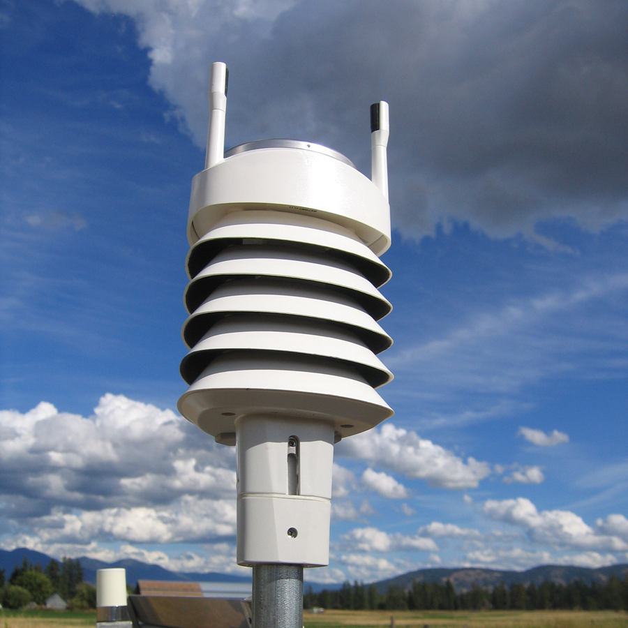
Meteorological instrument systems contains sensors for atmospheric measurements. For example, a subset of the NOTA GPS network uses a combination of Vaisala WTX510 and WTX520 units, which are low power devices with temperature, pressure, humidity, rain intensity, wind speed, and wind direction sensors. GPS and meteorological systems are good candidates for collocation because GPS and meteorological data are easily integrated into one data stream. Most of the meteorological systems in the NOTA network are configured for five-minute sample intervals and hourly downloads with the GPS data.
The meteorological data from these systems are used for augmenting weather forecasting as well as for hydrological studies. For example, the atmospheric pressure data at a site are used to separate the zenith total delay of precipitable water vapor (PWV) in the troposphere into the hydrostatic and wet components of PWV and the other met observables are compared with model results after PWV and other processing.
Tide Gauge Systems
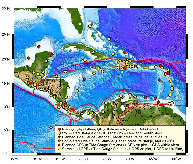
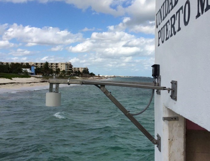
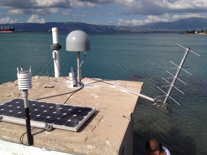
Tide gauges are instruments that measure sea level relative to a local geodetic benchmark. Two primary reasons for measuring sea level are observing global sea level change and sea level hazard event research. Acoustic, hydrostatic pressure and radar tide gauges provide precise relative sea level data but can be greatly influenced by variances caused by vertical land signals and the stability of the surface they are built upon. Furthermore, accurately tying relative sea level to a global reference frame is an ongoing challenge for geodesists. At selected tide gauge locations, UNAVCO has installed two cGNSS in the vicinity of the tide instruments in order to constrain these measurements within a global frame of reference. One cGNSS installed on the pier or structure that supports the tide instrument and a second cGNSS within five kilometers to provide a short baseline to a more stable reference time series. This layout provides a near real-time position of the tide gauge instrument, both relative to the potential changing apparent sea level height as well as the dynamic global reference frame.
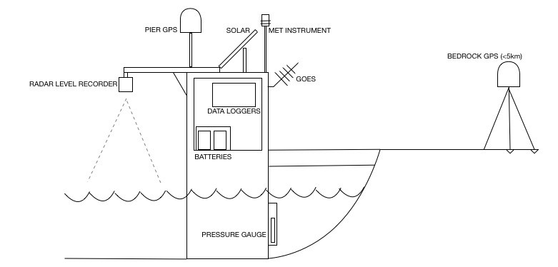
UNAVCO tide locations include Trimble NetR9 receivers with Trimble GNSS chokering antennas. cGNSS data undergo standard UNAVCO processing producing 15-second daily and 1-Hz hourly solutions. When possible, cGNSS locations also support real-time data streams.
Tide instruments supported by UNAVCO include the Sutron Radar LevelRecorder and INW PT12 Pressure Sensor with the Sutron XLite data logger. These instruments are configured to transmit 1 minute samples via GOES telemetry and current and archived data are available at the UNESCO-IOC tide gauge archive.
Monumentation Types
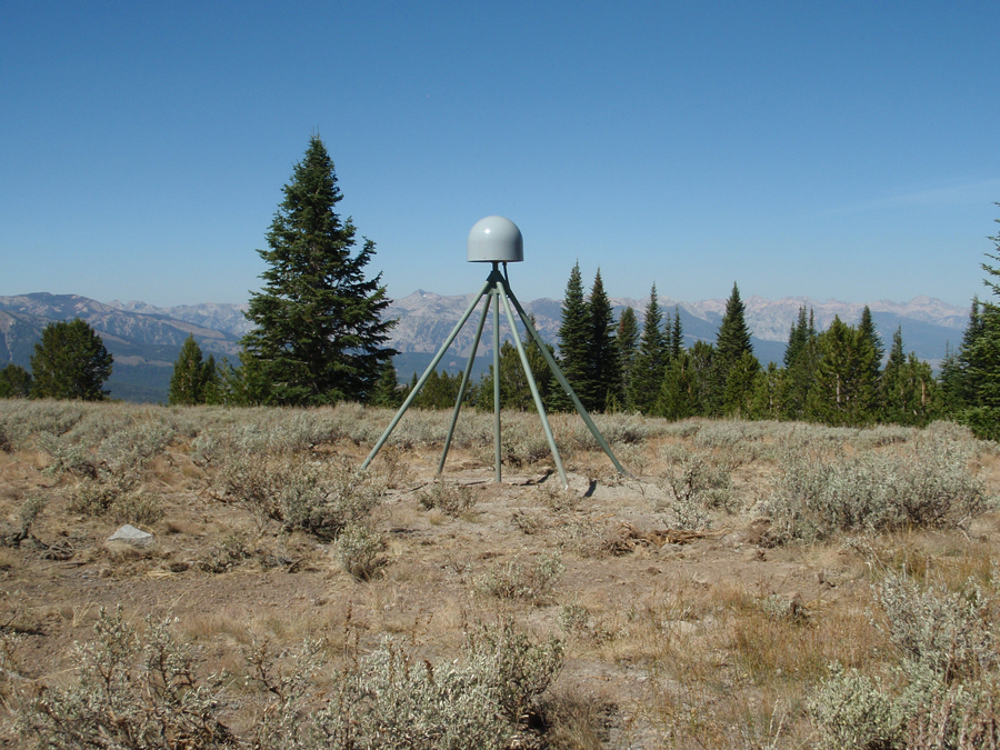
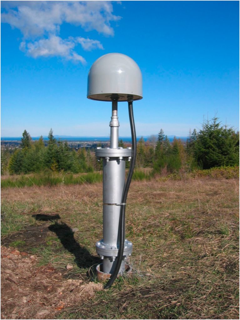
The monument for a GPS/GNSS site should be designed to provide a stable and securely anchored structure to which the GPS/GNSS antenna is mounted. UNAVCO has adopted and uses two primary types of monumentation: the deep-drilled, braced monuments (DDBMs) and the short-drilled, braced monuments (SDBMs). In addition to DDBMs and SDBMs are other special purpose monumentation such as the Alaska thermopile monument, the borehole strainmeter hybrid monument, and the building mount monument, which are used in special circumstances.
The DDBM is designed to create a highly rigid and immobile structure isolated from surface soil movement and cemented in place at depth. The monument consists of five legs (stainless steel pipes) placed and grouted into drilled holes, and welded together above the surface to create a “tripod” frame. Of the five legs, the center leg is vertical and the four other legs are installed at angles to brace the vertical leg. The holes are drilled to a depth of 40 ft with a truck or track mounted drill rig, and thus vehicle access to the site is required for this type of monument.
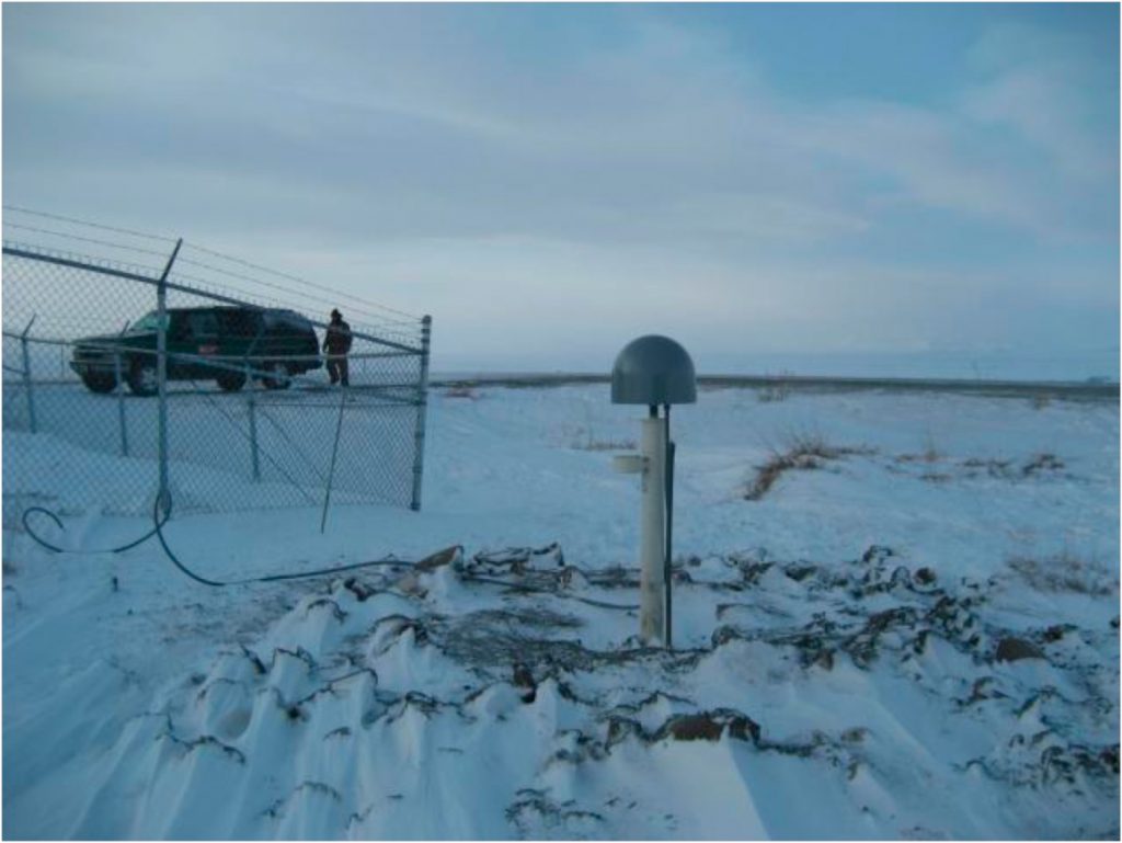
The SDBM is similar to the DDBM in appearance, but is used where competent rock is at the surface, and where cost and/or access issues prevent the use of a full size drill rig. The SDBM is composed of 4 legs (solid stainless steel rods), epoxied into rock to a depth of up to 6 ft, and welded together to create a “tripod” frame. The material and tooling needed to construct an SDBM can be transported with a single pickup truck, slung to the site via helicopter, or carried via horseback or even hiked in a short distance. With reasonably good conditions, a crew of two can install a station in two long days. Because the specified antenna height range is slightly lower than that of the DDBM, sky view and multipath obstructions, as well as snow pack, can be more problematic.
In the permafrost region of central and northern Alaska, ground conditions are such that neither the DDBM nor the SDBM will allow for solid anchoring to the sub-surface. There is generally not rock at these locations, and so the thermopile monument is used to achieve a solid bond to the always frozen permafrost layer. The monument consists of a single pressure vessel, filled with high pressure carbon dioxide. The thermodynamic properties of the carbon dioxide allow the monument to stay frozen in place during both the long cold winters, as well as the summer months when the upper layer of the soil thaws.
Where borehole strainmeters have been installed, it is often cost effective and relatively simple to install a GPS antenna mounted to the strainmeter casing, using a hybrid monument. The hybrid monument structure bolts directly to the 6″ strainmeter casing pipe, which is then reduced down to a 1.25″ nipple, which protrudes from the strainmeter equipment hut and allows attachment of the GPS antenna.
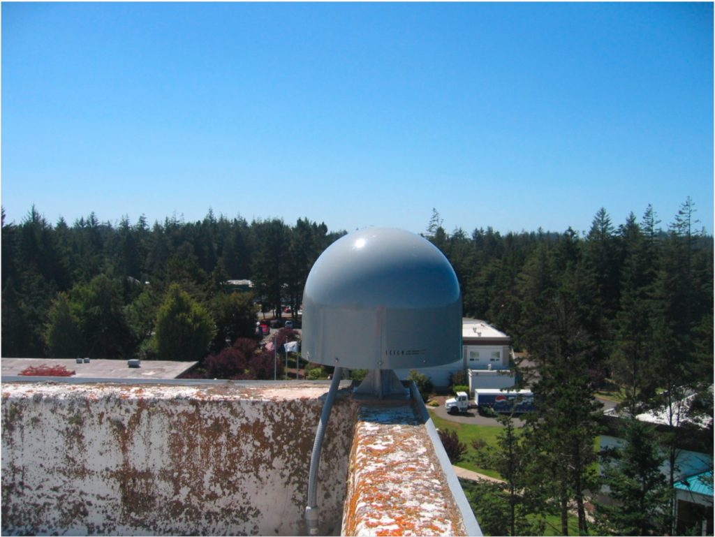
In rare cases, there may be times when none of the above monuments are suitable, generally due to an abundance of buildings and other structures in the area. In such cases, a GPS antenna can be mounted directly to the roof of a building with the building mount monument. This monument is secured to a corner or other stable portion of a structure with epoxy and short stainless steel legs. Ideal building candidates are well established, reinforced masonry structures, 2-5 stories in height.
For more information about monumentation types, please see the UNAVCO Knowledge Base on GNSS Monumentation.
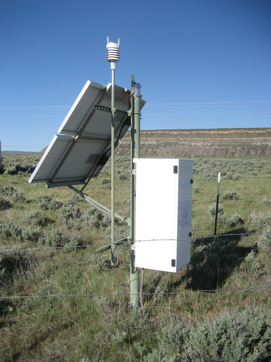
Power & Enclosures
GPS/GNSS permanent stations are typically powered either through a solar (photovoltaic) system, or a connection to an AC power feed, and use a varying number of batteries. Stations relying on solar power typically contain between 4 and 30 batteries, whereas those using AC power have fewer batteries to maintain constant power during brief power outages. Both systems supply continuous 12 volt DC power to a GPS receiver, communications device, and meteorological equipment. General system loads will vary from 4 to 24 Watts. Solar powered stations with power needs greater than 9 Watts are generally split into two DC systems, so that the communications equipment power draw will not affect the GPS power system.
Size and quantity of the power system components (enclosures, batteries and solar panels) will vary based on total load and location. There are generally four types of system configurations. Configuration usage is determined by cross referencing desired load with NREL minimum solar radiation data. The system break down is as follows:
- System Type 1: Single Enclosure, 1-2 battery, one to two solar panels (for DC systems) or 1 battery and one battery charger (for AC systems)
- System Type 2: Single Enclosure, 4 battery, two to four solar panels
- System Type 3: Separate Battery and Equipment Enclosures, 8-16 batteries, four to eight solar panels
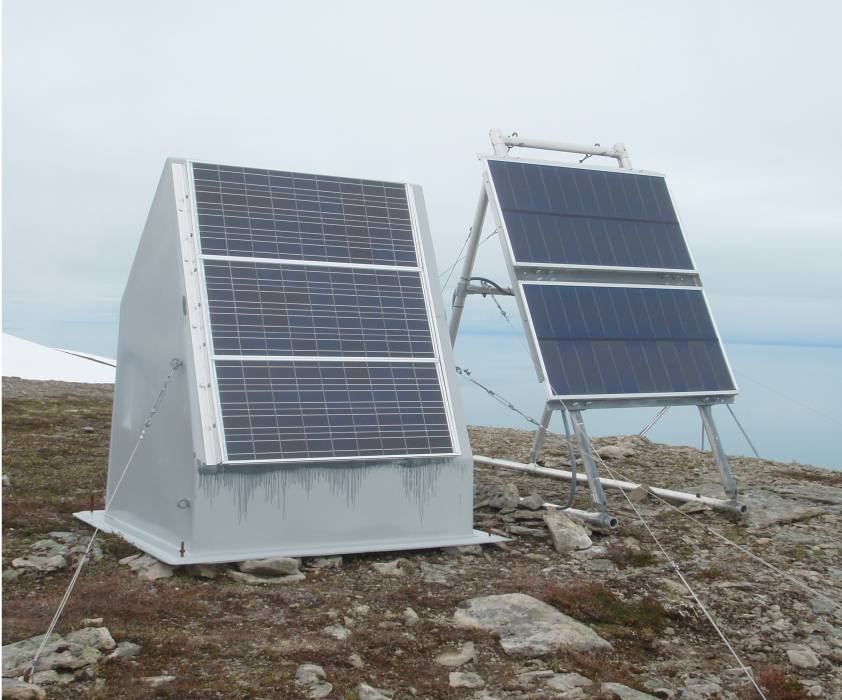
- System Type 4: Freestanding fiberglass hut used primarily in Alaska and some locations in the Pacific Northwest, 24-30 batteries, three to six solar panels
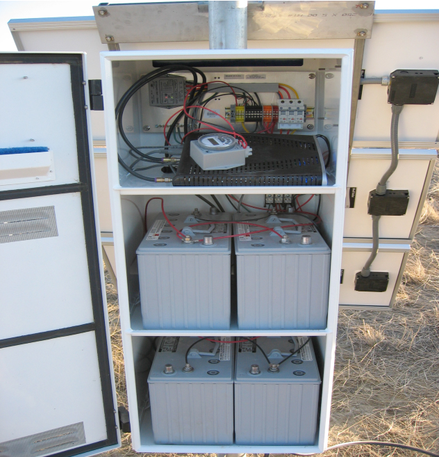
Power System Components
The above systems utilize a combination of solar panels, batteries, backpanel (consisting of AC/DC charge controllers, DIN rails, and circuit breakers), lightning protection, RF surge protection, and associated wiring to maintain sufficient continual voltage to the installed electronics. The enclosures that house the electronics and internal power system components are also an important part of the NOTA station. The vendors and specific models of these components may vary to a slight degree throughout the duration of major projects or with what is currently available, but generally these components are interchangeable with one another.
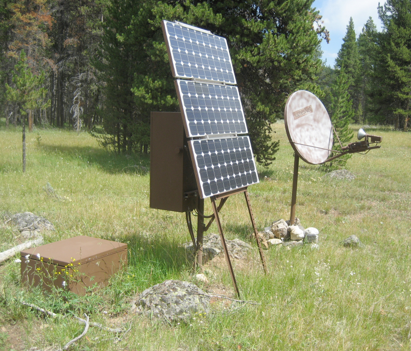
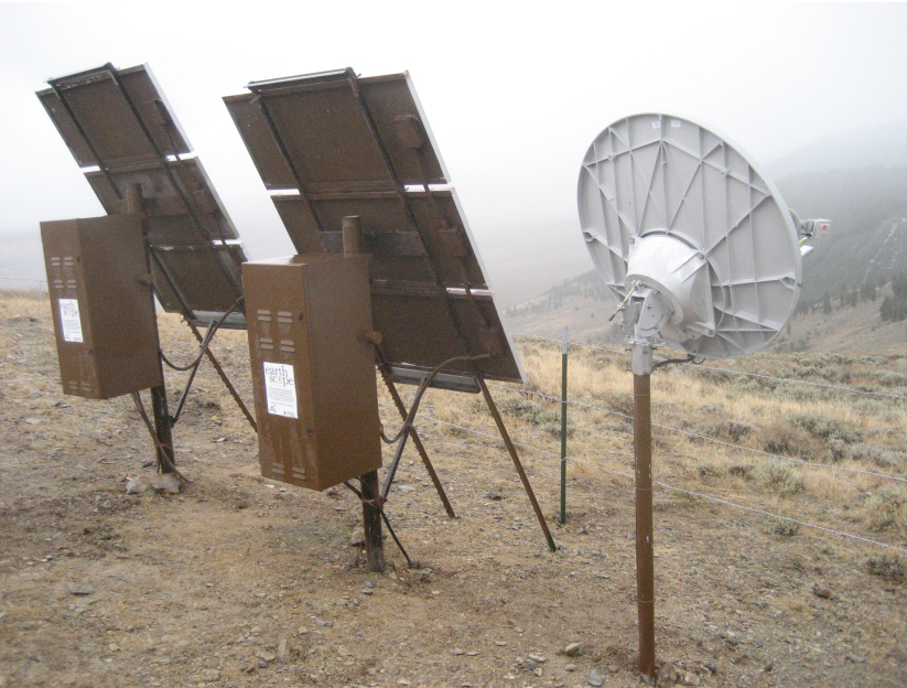
Solar Panels
Using solar panels to supply input voltage to DC systems has proven the most effective and reliable source of power. As opposed to wind turbines, solar panels are usually less affected by wind loads and icing, and are a better choice for remote installations. Solar panels are wired in parallel and connected to the backpanel via a solar isolation block, which incorporates a lightning protection device which is discussed below.
Lower 48 States in the US: For use within the continuous lower 48 states of the US, the initial panel of choice has been the Siemens SP-75, which output 75w and was of a standard frame size. Tamper-resistant panel frames are built to dimension for the panels. After Siemens discontinued the manufacture of these panels, other vendors were used that produced panels of this standard frame size, including BP, GE, and others. The output of the panels made by the various vendors varied from 72-80w. Availability of these panels can fluctuate, making large orders important when available.
Alaska: Originally for the PBO GPS Network in the Alaska, the panel of choice was a 60w shatter resistant panel, recommended by other network operators already working in the state. The shatterproof design was thought to be superior to conventional panels due to the extremely high wind loads, combined with heavy icing, that apply large forces on the face of the panel. Unfortunately, these panels did not perform as expected in the field. Problems arose with the surface of the panel clouding, greatly reducing the solar radiation that actually made it to the photovoltaic cells, in addition to the coating on the panel face degrading which allowed water and particles to enter the cells and damage them. In addition, the shatter resistant panels were ironically no more shatter proof than conventional panels.
Sharp 80w panels are deployed in Alaska, replacing the 60w panels. The DC stations in Alaska do not generally utilize tamper resistant panel mount, and so conforming to the standard panel frame size is not critical. The Sharp 80w panels are somewhat narrower than the SP-75 standard used in the lower 48, and are attached to huts and swingsets with a custom mounting system consisting of angle aluminum bolted to the panel and then to the hut, which securely holds them in the face of high winds.
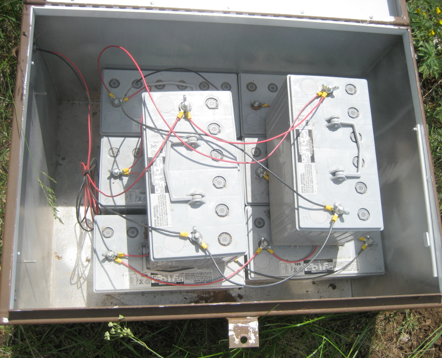
Batteries
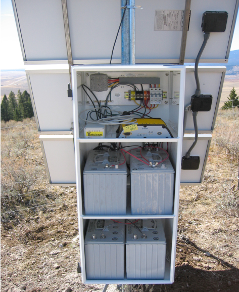
The standard specification used by NOTA for batteries at both DC and AC stations is the 12V, 110 amp-hour deep cycle gel cell battery, specifically made for slow charge/discharge situations. These batteries perform well across a broad temperature range, and do not spill corrosive contents if a cell is punctured. The batteries in a given system are wired in parallel and connected to the backpanel. The terminals of these batteries vary according to customer specifications, and come in flag, stud, and threaded stud configurations. For ease of installation in space restricted enclosures, the threaded stud terminals have become the choice of NOTA. The type 1,2, and 3 systems referenced above utilize enclosures that are built to specifications that snugly house between 2-4 batteries in a lower compartment, isolated from the upper electronics compartment. Freestanding enclosures built to house solely batteries are also deployed at NOTA stations, and hold either 8 or 16 additional batteries for high load applications. In Alaska, the fiberglass huts hold many more batteries, up to 30, which allows for continuous power throughout the sunlight deprived winter. This large number of batteries is often divided into separate parallel strings, both wired to the battery blocks on the DIN rail.
UNAVCO’s current procedure to replace all batteries at a station every 5 years, generally before they start to seriously degrade in performance. It should be noted that some stations in existing networks have been observed to operate close to 10 years on a set of properly installed batteries.
Charge Controllers
DC and AC charge controllers regulate the power supplied to the batteries, shutting off the charging when the batteries reach full capacity, and then resuming charging when the batteries begin to discharge (if there is available power via solar panels in DC systems). The charge controllers themselves draw a small amount of power (approx. 6mA current), a factor not usually included in system selection.
DC Systems
The charge controller used in NOTA DC powered stations is the Flexcharge NC30L12. This unit is robust and is tolerant of a wide range of atmospheric conditions. It charges batteries to a maximum voltage of 14.25v, and resumes charging when batteries drop to 13.70v. The unit also features a low voltage disconnect (LVD) that eliminates power to the system load circuit when the batteries drop below 10.92v, which reduces the possibility that batteries are drained completely dry, a scenario that generally results in severely reducing the battery lifespan. The charge controller is mounted to the backpanel, and wired to the circuit breakers.
AC Systems
For AC systems, a larger charge controller is installed to convert the 120v AC current into 12v DC current for battery charging. The charge controller selected by NOTA for use is the Iota DLS-15, which provides a small float-charge to keep the batteries near optimum charge levels when there is constant AC power. In the event of an AC power outage that results in battery discharge, the unit will charge the batteries more rapidly when power is restored.
DIN Rails and Circuit Load Breakers
On the NOTA backpanel, the power distribution is accomplished through a compact set of DIN rail connections that are separated into 4 blocks; solar power input, batteries, load, and ground (negative). The three positive blocks each has an associated circuit load breaker that allows the components to be turned off separately, and additionally prevents spikes from propagating through the system. The solar and battery breakers are 50A, while the load is a smaller 15A breaker.
Lightning Protection
To protect the DC power system from surges due to atmospheric static discharge via the solar panels, a lightning protection device is installed on the exterior of the enclosure. The protection device chosen by NOTA is the Delta LA-302 lightning arrestor. It is wired in common with the solar panel input to the solar isolation block. It is rated to clamp a 50,000A surge in 25 milliseconds, and will clamp up to a maximum of 100,000A surge but will be destroyed in the process. It should be noted that no lightning protection can truly guard against a direct lightning strike, and in such an event, it is likely that some or all of the electronics in the enclosure will be destroyed.
RF Surge Protection
To limit power surges traveling down the various coaxial antenna cables that are connected to the GPS chokering antenna and communications antennas, in-line surge protectors are installed inside the enclosure, mounted to the bottom of the top equipment shelf and grounded via the enclosure itself. NOTA uses the Huber-Suhner 3402 series of RF surge protectors, which protect on frequencies up to 2.5 GHz, and can stop a surge of up to 30kA a single time, or multiple surges of up to 20kA. The mechanism at work is a small gas filled discharge tube inside the Huber Suhner device, which sparks excess current over to ground (leveling charge in both conductors of the coaxial antenna cables) when a surge travels down the cable. After the surge has discharged, the gas capsule reverts to a near infinite resistance, once again separating the two conductive elements of the coaxial cable.
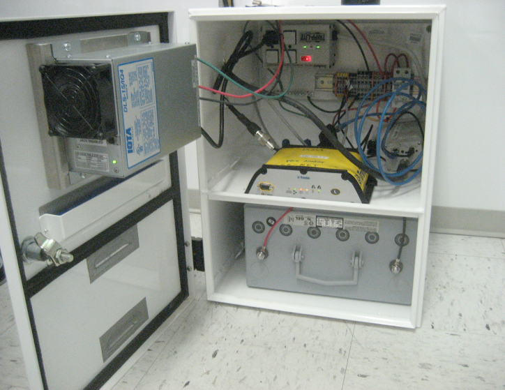
Enclosures
The various systems described above utilize different equipment enclosures based primarily on the number and size of the electronic devices and the number of batteries to be installed. They are designed to be weatherproof, to hold one of two different backpanels, and to utilize a standard key.
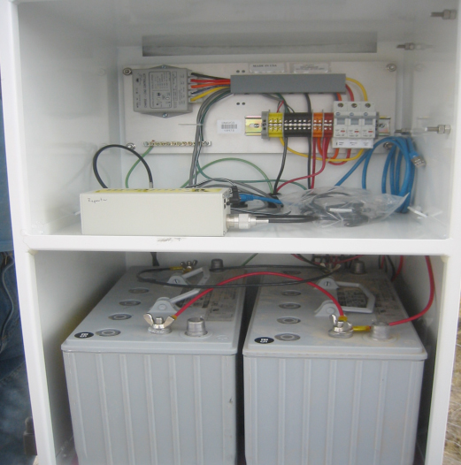
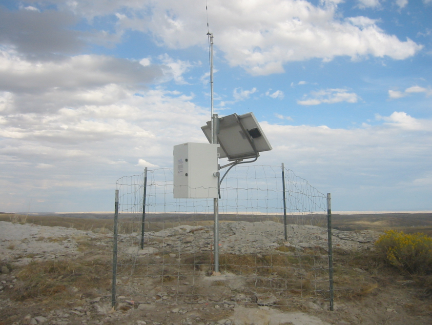
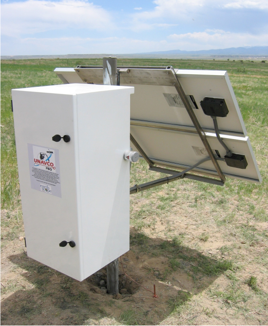
Lower 48 States in the US: System types 1, 2, and 3 are generally found at most stations in the lower 48 states and hold between 1 and 20 batteries in total. These enclosures are constructed from aluminum, and then powder coated with a durable white finish. On the door of each enclosure is a decal that presents information about the GPS station, as well as contact information for those wishing to learn more about NOTA. The type 1 and 2 system enclosures are divided into separate compartments, either two or three shelves. The top shelf is standard, and contains the AC or DC backpanel and holds the GPS receiver and communications equipment, and is isolated from the lower shelves via weather resistant strain relief pass-throughs. The lower shelves hold the batteries and also have knock-out ports for the entry of antenna cables and solar panel leads, the solar isolation block, and the gas capsule side of the Huber Suhner RF surge protection devices. Affixed to the exterior of the lower compartment are the lightning protection unit and the grounding lug, which is connected via copper wire to the ground rod. These enclosures are mounted to 2-4” pipe masts via tamper resistant brackets, and have a door with 2 locks, that can be lifted off its hinges to allow engineers to work on the enclosure components unhindered.
The type 3 systems can include a type 1 or 2 enclosure, as well as a separate stand alone battery chest that holds either 8 or 16 additional batteries. These battery chests are positioned on the ground near the primary enclosure, and are wired to the battery portion of the DIN rail via 10 gauge wires routed through a weather proof conduit.
Alaska: The fiberglass huts used to house the large number of batteries and Alaska style backpanel are specifically designed for use in Alaska and other low solar radiation locations, such as Mt Saint Helens. The hut is weather resistant and is more durable than the aluminum enclosures. Three of the Sharp 80w solar panels can be mounted to the back portion of the hut, which allows the engineers to fully assemble the solar power system of the hut prior to emplacement via helicopter sling line. Once in position, the hut is loaded with up to 30 batteries, and the electronics are installed. The hut is generally secured to the ground with all-thread rods driven through the corners of the bottom flange and into the ground, as well as with high tension guy wires secured to rock bolts or duck-bill anchors. Additionally, extra solar panels can be mounted to a free standing aluminum frame, known as a swingset, to give the station extra power in low sunlight conditions. However, these swingsets have repeatedly failed in high wind locations, which was one factor that precipitated the switch from 60w to 80w solar panels mounted directly to the hut.
For more information about power, please see the UNAVCO Knowledge Base on GNSS Station Power.
For more information about enclosures, please see the UNAVCO Knowledge Base on GNSS Enclosures.
Cellular Technologies
Cellular Internet Gateways and Routers
Through the use of cellular modems and cell phone internet gateways UNAVCO in the 21st century has been able to take advantage of this leap in technology and the ever growing cellular data network to reliably and inexpensively transfer data from remote stations to other locations, such as back to Boulder, Colorado.
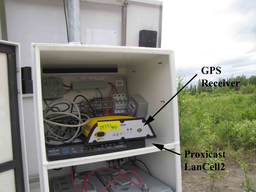
While there are a number of companies offering combination gateway/routers to allow for access to the Internet using the various cell phone providers consumer grade data networks and a number of which have been used by UNAVCO on other projects. For NOTA, it was decided to utilize Proxicast LanCell products since the mobile gateway/routers manufactured by Proxicast are particularly well suited to NOTA for several reasons. These include the fact that they are extremely easy to use, they have been proven history of reliable operation in remote areas under harsh environmental conditions and they have a relative low operational cost when compared to other options for internet connectivity. In addition to this they also have the advantage of having a built in router that can be utilized to connect multiple stations via a VPN for secure data transfer.
Proxicast manufactures two mobile Internet combination gateway/routers the LanCell and the LanCell2. NOTA utilizes both the first the generation Proxicast LanCell Mobile Gateway/Router and the next generation LanCell2 Gateway/Router. Though they both use a cell phone connection to access the internet and both include routers that are VPN capable there are some notable differences between the two units and it is worthwhile to point out the features of both to illustrate these.
The first generation LanCell uses a SIM card, like those used in handheld cell phones and because of this it is limited to connecting to the internet using older cell data technologies. Though they are quite reliable, this means that they are fairly slow and in some instances have been made obsolete where they are no longer compatible with the latest wireless standards in place. As a result of this, recently we have been migrating to the latest generation of wireless gateway/router manufactured by Proxicast, the LanCell2. Unlike the LanCell1, the LanCell2 uses a PCMCIA instead of a sim card to connect to the internet and is compatible with a variety of different services that utilize the latest generation of wireless data standards. In areas where wireless broadband is available with the LanCell2 we are able to stream data in real time from our stations. Additionally, there are several new features unique to the LanCell2 such as its capability to act as a wireless access point, a built in signal strength meter and programmable soft reboot timer.
In terms of power consumption, both units run on a 12 volt power supply and are easily integrated with the other components at most remote stations. Power consumption is 5W to 8W for the LanCell2 and 6W to 14W for the LanCell1. Typically, these are left running continuously at remote stations, though, if power is a concern, they can be put on a timer to reduce power consumption.
For more information about cellular communication technologies, please see the UNAVCO Knowledge Base on Cellular Modem Summary.
Land-Based Communications
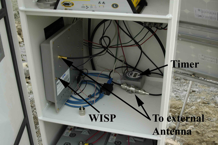
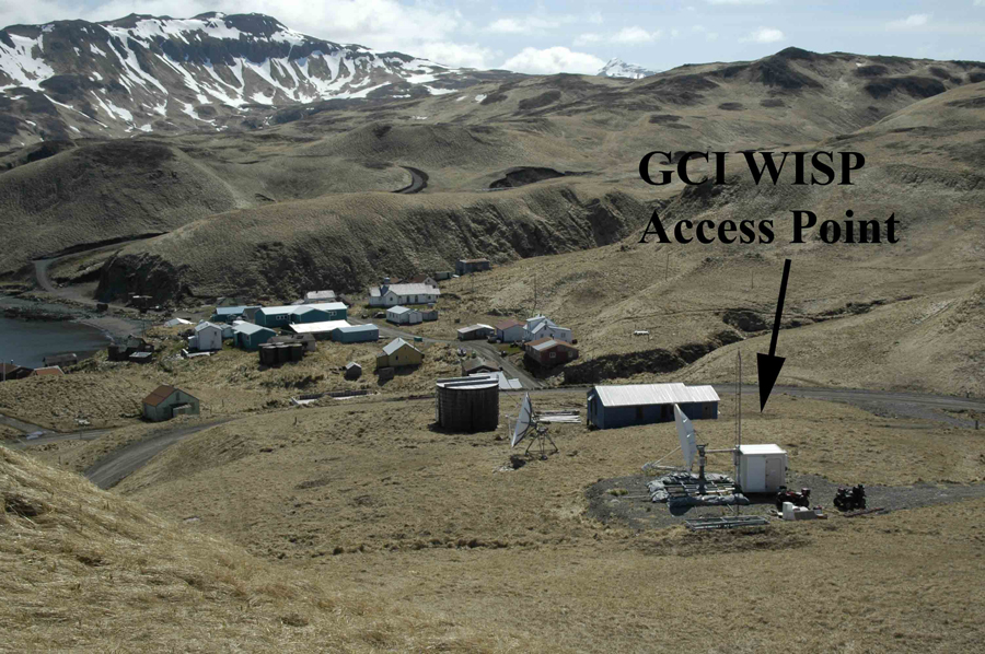
Wireless Internet Service Providers are common in more rural and remote areas of the US where Cell Phone, or wired internet access is unavailable. They are simply put a secure wireless internet connection similar to what one would use in the home, but with a more powerful transmit antenna. In most cases the primary connection is either a microwave link from an area where hardwired access is available, or a shared satellite internet connection, as is the case in most of rural Alaska where NOTA has many stations. Due to the remote nature of these WISP networks the level of maintenance and therefore reliability of the connection varies quite a lot between different locations. Despite this they can sometimes be an attractive alternative to a stand alone VSAT and can be worked with in locations where there are no other options and a VSAT solution is not workable and/or is not practical.
The majority of WISPs that are currently deployed in the NOTA project are in the Alaska Region in remote locations where they are the only viable option for data transfer. All of these WISPs are operated by a single wireless provider GCI. GCI, as is typical with WISP providers, has in some locations provided great service and in others it has been very intermittent. Even where connections are reliable, data transfer rates are quite slow and we are limited to collecting daily files from stations with no option for streaming.
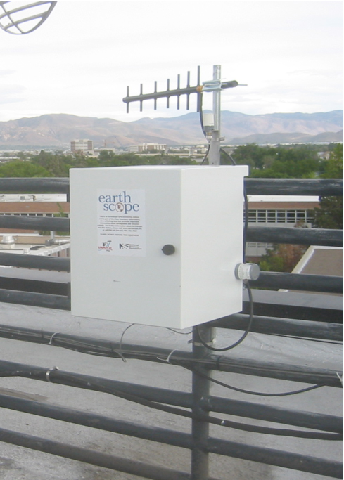
The GCI WISP hardware that has been used in Alaska consists of a combination antenna and receiver. There is no separate power supply, since the device is powered by 12 volt power over Ethernet. In a normal consumer installation the entire unit is placed outside and an Ethernet cable is run inside to a computer for internet access. In our installation we have modified the WISP to use an external high gain yagi antenna that can be oriented directly towards the access point for a better connection. Additionally, we have found that putting them on a reset timer that actually activates the reset function of the WISP as well as power cycling the unit has helped with long term reliability. The timer must be set to reset the unit several times a day for this to work well. They run on 12V DC power and fit easily into a standard NOTA metal enclosure box, or hut.
For more information about land-line modem communication technologies, please see the UNAVCO Knowledge Base on Dial-up Landline Modem Summary.
Radio Communications
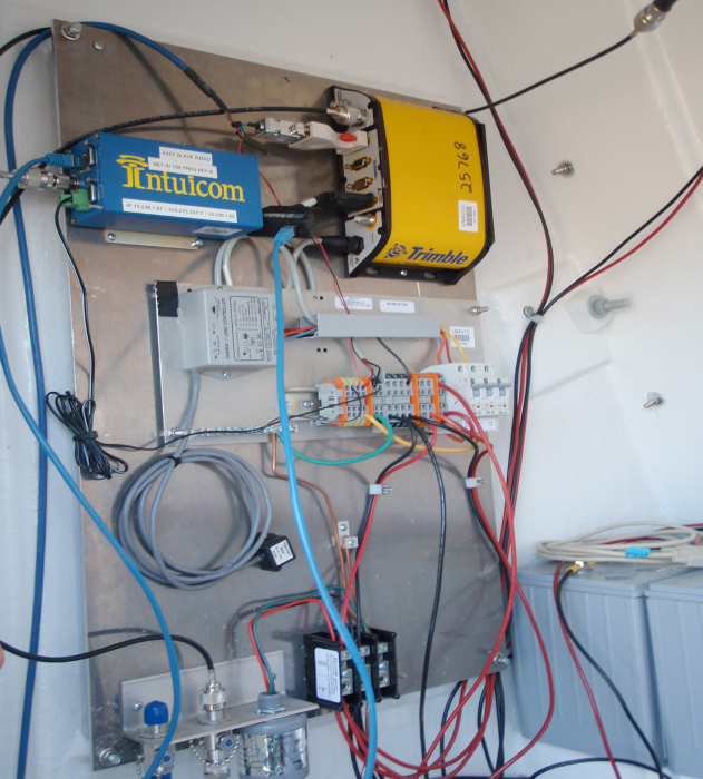
Due to the remote location of some stations, an Internet connection may not be available. However, if a station has a line of sight to another station or location that does have reliable Internet access, the best option can be to establish a radio telemetry link from the station without an Internet connection to another site where an Internet connection is available. It is also advantageous to combine multiple stations via radio link into one network with a common Internet connection, cutting down on the number of Internet connections that need to be maintained and paid for. In the NOTA GPS Network UNAVCO utilized Intuicom 900MHz spread spectrum radios for the majority of installations. These radios are compact, very rugged, have relatively low power consumption, are easy to use and have exceptional long range transmission characteristics.
Radio networks can be set up two different configurations. These are Point-to-Point and Point-to-Multipoint. A point-to-point network consists of a radio located at an Internet gateway, linked to a single remote end point station. A Point-to-Multipoint network consists of one gateway radio located at the Internet connection, linked to end point radios located at the remote GPS stations. Sometimes if there is not direct line of sight between a station and a gateway it is necessary to install a repeater radio in a location that has line of sight to both. In these cases it is often preferable to set up a series of point to point links, as this tends to be more reliable and allows for faster data transfer between stations.
Radio Types
The following table outlines the published specifications for some of the common types of radios used by UNAVCO.
| Manufacturer | Model | Radio Frequency | Useful Range | Power Consumption | Serial Capability (Y/N) |
|---|---|---|---|---|---|
| Intuicom | EB-1 | 900 – 928 MHz | 60 miles LOS | 6 W max | N |
| Intuicom | EB-3plus | 902 – 928 MHz | 60 miles LOS | 6 W max | Y |
| Intuicom | EB-6plus | 902 – 928 MHz | 40 miles LOS | 6 W max | Y |
| Intuicom | EB-58 | 5.8 GHz | 60 miles LOS | 7 W+ | N |
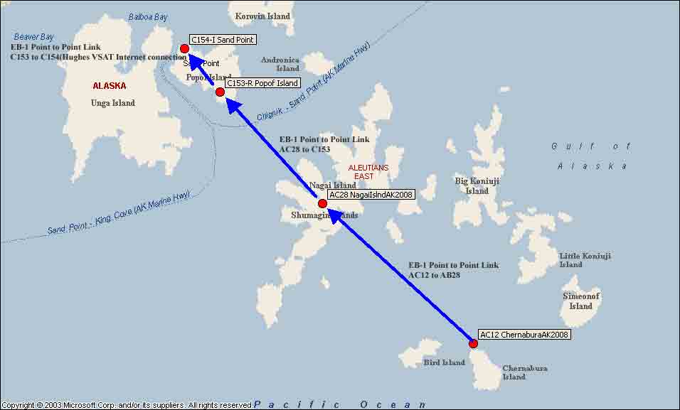
Example Radio Network Topology
This network links AC12 Chernabura, AC28 Nagai Island and AB06 Sand Point via an Intuicom EB-1 Point to Multipoint radio network to a common Hughes VSAT internet connection at C154 in Sand Point, AK that is co-located with GPS station AB06. The gateway radio is located at VSAT at Sand point; there are end point radios at AC28 and AC12. A repeater radio located a C153 relays the links from AC28 and AC12 over the topography that obstructs line of sight between these two stations and C154.
Example Radio Installations and Components
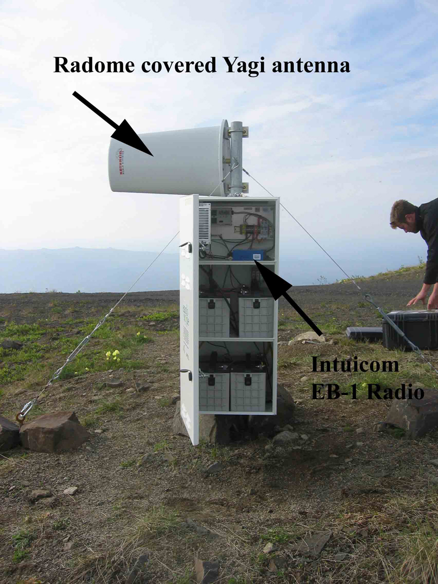
AB25 Tatalina Radio Repeater — AC Powered site with an aluminum enclosure and an externally mounted radome covered yagi (recommended to for all external applications where possible).
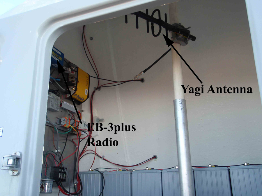
AV24 Unimak Volcano GPS Station — A typical data telemetry radio installation inside a standard NOTA hut. The EB3plus radio in this location is mounted to an aluminum back panel; it is wired to the antenna that is attached to a mast installed in the center of the hut.
For more information about radio communication technologies, please see the UNAVCO Knowledge Base on Radio Modem Summary.
Satellite Communications
Very Small Apeture Terminal (VSAT)
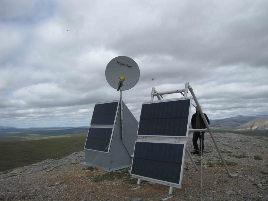
In many remote locations the only practical communications method is through a Very Small Aperture Terminal (VSAT) satellite system. The two satellite Internet providers used by NOTA are HughesNet (formerly called Direcway) and in Alaska, several sites use the Starband system. Note that the installation document that is linked to from this page describes a typical HughesNet installation. The only significant difference in installation procedures for a Starband is that the Starband system does not have a pointing interface installed on the modem. For this reason it is necessary to have a separate outdoor pointing interface, typically a “Bird Dog” satellite meter is utilized to tune the dish.
Each VSAT communication installation uses a relatively small (“very small aperture” means less than 3 meters in diameter) radio-reflective paraboloid dish with a transceiver mounted in front of it that is pointed toward a single GEO satellite about 35800 km above the Earth’s surface at the equator.
When possible, a satellite with longitude fairly close to that of the station should be selected. This way, the satellite will be to the south at the highest possible elevation. However, the signal footprints of satellite transponders can point at various angles, so that the strongest signals are not always from the closest satellite. Usually, the broadcast company assigns satellites based on usage patterns as well as the particular ground location. At high latitudes, pointing to a satellite near the station longitude becomes more important. At 80° latitude (north or south), even a satellite directly to the south is essentially on the horizon, so using VSAT at more than 70° is difficult at best.
Though, it is certainly not neceessary to understand how the geostationary orbit works. It can be useful to visualize what the orbit looks like from various latitudes. During recon of a potential VSAT site, one can quickly gauge which particular spots will have a clear shot at a satellite. During installation, it is easier to reality-check the dish pointing and polarization values.
At the equator, the geostationary orbit is a “straight arc” from due east to directly overhead to due west. At higher north latitudes, the arc becomes a curve with its high point further and further to the south. Before doing recon for a VSAT site, and certainly before committing to a final dish location, the pointing azimuth and elevation of the available satellite(s) should be noted. In the field a compass and clinometer can be used to verify that the intended satellite is in unobstructed view. A useful web-based application to find pointing parameters, incorporating Google Maps, can be found here.
At most NOTA stations that use VSAT, the dish is mounted on the top of the enclosure pole, and the modem (currently called the DW7000) is placed in the top enclosure compartment along with the NetRS GPS receiver. At locations where there is no enclosure post a secondary post is either attached to the side of the enclosure hut or another post is installed in the ground. As noted above, the first siting requirement is that there is a clear line of sight to the intended satellite. This is determined by finding the sky location of the satellite and making sure that no ground obstructions block that spot, and that no trees or buildings are likely to become obstacles during the life of the station. In one case, on an oil platform off the southern California coast, the originally reconned dish location was blocked by an escape pod (enclosed lifeboat) hanging from a higher deck. Be aware that the true beam path is not the apparent direction that the dish is pointing, by about 20°. To avoid having the transceiver block a large part of the signal, it is mounted off-center. With the typical vertical receive, horizontal transmit setup, this means that the transceiver is low and bounces the signal upward off the dish. However, if the transponder is polarized for horizontal receive, the transceiver will be to the side of the dish, and the pointing azimuth will be around 20° from where the dish appears to be facing.
Broadband Global Area Network (BGAN)
BGAN communication uses a satellite constellation, operated by Inmarsat, using three geostationary satellites providing near-global coverage. Satellite communication via BGAN uses a modem-antenna unit about the size of a laptop computer. Since the communication is with one of the three GEO satellites, the unit needs to be roughly oriented, usually in a fixed position, for optimal data transmission.
UNAVCO BGAN installations currently use the Hughes Broadband Satellite IP Terminal. Installations done by UNAVCO typically incorporate a timer switch to limit the BGAN modem on-time to reduce power consumption at the site.
Iridium
The Iridium satellite constellation, developed by Motorola between 1993 – 1998 and now owned and operated by Iridium Communications Inc., consists of 66 active LEO satellites and additional spares at a height of approximately 781 km above the Earth at an orbital inclination of 86.4° in six orbital planes with 11 active satellites in each plane. Satellite communication via Iridium allows users to place voice and data calls from remote locations any place in the world using a handset about the size of a cordless home phone. Calls can be made to land line telephone systems, cell phones, or other Iridium phones. Internet access is also available through Iridium’s ISP or other ISPs, using an L-Band Transceiver (LBT) at the remote site in place of the Iridium phone. This is the only communication system with global coverage, which is especially useful for remote sites in polar regions or other sites where no other communications options are practical.
Iridim communication allows up to 2400 bps which is suitable for normal rate GPS/GNSS data downloads of remote sites. At each site a Iridium tranmitter/receiver modem with omni-directional antenna needs to be installed. The power consumption is about 1.0 W when downloading a typical 1 MB data file per day. The Iridium modem is sensitive to antenna cable losses thus requiring overall cable loss between the modem and antenna to be < 3dB. Installations done by UNAVCO typically incorporate a timer switch to periodically reboot the Iridium modem. Proximity of the Iridium antenna to the GPS/GNSS antenna has been known to cause RF interference with the relatively weak GPS/GNSS signals when the Iridium modem is transmitting.
For more information about radio modem communication technologies, please see the UNAVCO Knowledge Base on Satellite Communications Summary.
Home
- Permanent Station Support
- Last updated: 6 May 2022